
Technical Information
Gearboxes and Transmissions
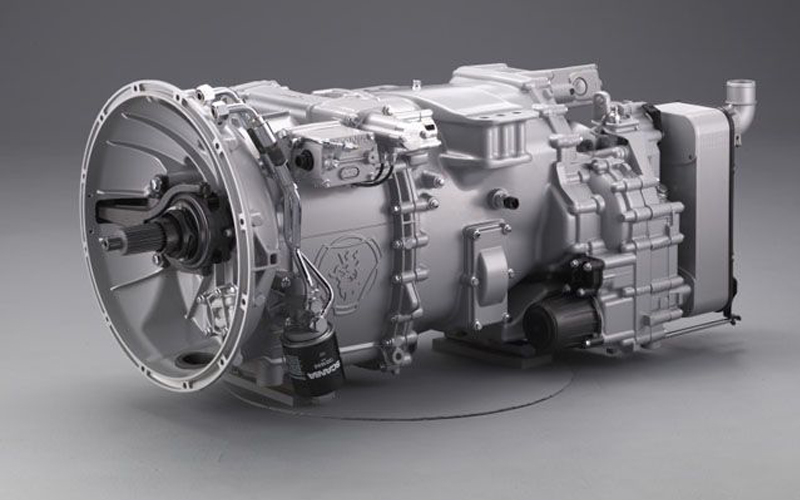
The most basic definition of a gearbox is that it is a contained gear train, or a mechanical unit or component consisting of a series of integrated gears within a housing. In fact, the name itself defines what it is; a box containing gears. In the most basic sense, a gearbox functions like any system of gears; it alters torque and speed between a driving device like a motor and a load.
The gears inside of a gearbox can be any one of a number of types from bevel gears and spiral bevel gears to worm gears and others such as planetary gears. The gears are mounted on shafts, which are supported by and rotate via rolling bearings. The gearbox is a mechanical method of transferring energy from one device to another and is used to increase torque while reducing speed.
Gearboxes are used in many applications including machine tools, industrial equipment, conveyors, and motorised vehicles.
In motor vehicles, the gearbox or transmission is generally connected to the engine crankshaft via a flywheel or clutch or fluid coupling. Because an internal combustion engine cannot run below a particular speed. The gearbox provides a selection of gears for different driving conditions: standing start, climbing a hill, or cruising on level surfaces. The lower the gear, the slower the road wheels turn in relation to the engine speed. The output of the transmission is transmitted via the driveshaft to one or more differentials, which drives the wheels.
Most vehicles with manual transmissions have five or six forward speeds and one reverse, some heavy goods vehicles can have as many as eighteen different shift variations as well as a reverse position. The gear lever, operated by the driver, is connected to a series of selector rods in the top or side of the gearbox. The selector rods lie parallel with shafts carrying the gears. The most popular design is the constant-mesh gearbox. It has three shafts: the input shaft, the layshaft and the mainshaft, which run in bearings in the gearbox casing. There is also a shaft on which the reverse-gear idler pinion rotates.
The engine drives the input shaft, which drives the layshaft. The layshaft rotates the gears on the mainshaft, but these rotate freely until they are locked by means of the synchromesh device, which is splined to the shaft. It is the synchromesh device which is actually operated by the driver, through a selector rod with a fork on it which moves the synchromesh to engage the gear.
On some vehicles an additional gear, called overdrive, is fitted. It is higher than top gear and so gives economic driving at cruising speeds. In a constant battle for economy and performance the gearboxes/transmissions in heavy goods vehicles are fitted with “Range Change” and/or a “Splitter”. Also known as a GP and GV respectively. These adaptations do exactly as there descriptions imply.
Splitter Unit: Compressing the Gear Sequence.
A splitter always leads to a compression of the gear sequence and can be fitted before or after the main gearbox/transmission. The gear step in the splitter unit is less than that of the main gearbox. The number of gears in the main gearbox is multiplied by the number of gears in the splitter unit. The splitter unit is normally fitted with two gears. In practice, front-mounted splitter units are almost always used. The reason for this is that front-mounted splitter units only have a small ratio change of approximately 1.1 to 1.2. This means that the rear-mounted main gearbox is loaded either with only a slightly higher torque, or in the case of a speed-increasing ratio, even with a lower torque than without a splitter unit. If the splitter unit is rear-mounted to the main gearbox, it must be designed for the highest torque multiplication reached in the main gearbox. That is a more expensive solution than a front-mounted splitter unit.
Range Change Unit: Expanding the Gear Sequence
The function of a range change unit is to expand the gear sequence. This is achieved by the ratio step in the range change unit being as big as the range of ratios in the main gearbox, multiplied with the gear step in the main gearbox . The gear sequence with the range change unit engaged follows smoothly on from that of the main gearbox. Overlaps in the ratios of individual gears are avoided by using geometrical gear steps. Range change units are always speed-reducing. The torque multiplication in the range-change unit amounts to approximately iR =1: 3−4. If the range-change unit was designed to be front-mounted, the high torque values would pass through the main gearbox. The range-change unit is therefore always fitted at the output end of the main gearbox. The range-change unit can be of countershaft design or a compact planetary gear unit.
As the drive for more economical vehicles and driver friendly solutions increase the technology from passenger vehicles filter down into the commercial vehicle sector. Depending on how their idler gears are positively locked to the shafts manual transmissions can be subdivided into non-synchronized constant-mesh transmissions and synchronized transmissions. They can also be divided by their shifting system into direct shifting, indirect shifting, automatic shifting and automated manual shifting. The latter being the most popular system in the current market. Automated Manual Transmissions (AMT) commercial vehicle have had level 4 automation since the end of the 1990s. This level of automation is characterised by an auto-mated moving-off element, automated clutch engagement in gear shifting, automated gear change and data communication between the engine control unit and the transmission control unit. Through this total clutch automation, the clutch pedal can be disposed of entirely, thus allowing for a two-pedal system in commercial vehicles with acceleration and brake pedals. In addition to the automatic mode, a manual mode enables the driver to intervene at any time.
The automation of manual transmissions offers many ad-vantages, the most important of which are:
- a High level of efficiency comparable to a manual transmission,
- Improved driving comfort as a result of relieving the driver of engaging the clutch and shifting,
- Improved driver alertness in road traffic,
- Reduction of life-cycle costs through: decreased clutch wear, decreased fuel consumption through the use of an optimised driving strategy (selection of shift programmes),
- Increased protection of components through the prevention of shifting misuse (transmission and clutch protection).
- Transmission control without rods and cables by means of a drive selector, which means: reduced noise in the cabin, as there is no mechanical connection between the gearshift lever and the transmission.
- Optimised packaging, as the rod shifting system and the clutch pedal are left out, which means a more simple and cost-effective assembly.
- A disadvantage of automated manual transmissions is power interruption, but since the shifting times of modern commercial vehicles are short, this is accept-able for road traffic.
The technology is ever evolving and OEM’s are continually improving and refining the systems in use. Bringing new systems to the market and improving the use of gearboxes/transmission in the future.
Retarders
A retarder is a device used to augment or replace some of the functions of primary friction-based braking systems, usually on heavy vehicles. Retarders serve to slow vehicles, or maintain a steady speed while traveling down a hill, and help prevent the vehicle from "running away" by accelerating down the hill. This is a critical safety feature and is especially useful in maintaining the vehicles braking efficiency.